Designing systems
Engineering is rarely done in isolation. When designing complex assemblies, the greatest challenge isn't optimizing a single panel or beam; it is managing the hidden web of constraints that bind components together. In traditional design, considering simultaneously all these interactions leads to long, iterative cycles of redesign.
In this study, we shift the focus from the part to the system. We explore how Braid's AURA reasoning engine can tackle a design problem by treating inter-component couplings as primary design variables. By generating subassembly components at the same time and not in isolation we demonstrate how to handle complex geometric and manufacturing constraints, effectively closing the loop on a historically manual process.
The interdependence of geometry
Most discussions of automated design treat the part as the unit of work: a bracket, a beam, a panel or even a chassis considered as a single entity. That is a reasonable simplification, because the constraints on a single part are localized: the loads they have to carry, the design envelope, the materials or the target manufacturing process.
However, real engineering rarely stops there. Parts are belonging to assemblies and once you cross that boundary the constraints are not purely local anymore. The geometry of one component will bound the design space of the surrounding components and loads will cross the interfaces between the parts. Components in an assembly cannot be designed independently and combined afterwards. They have to be designed against each other.
This is where a significant amount of the engineering time in a real design effort goes, and it is why design cycles are long. A generator solving the per-component problem well can produce parts that are locally excellent but inconsistent as the assembly level. Resolving them means going back to the drawing board: redesigning a component, perturbing its neighbours, redesigning those in turn.
This loop is what happens when a coupled problem is solved as though it were a set of independent ones. So the interesting problem is not generating a part but generating the part given the interactions with all the components around that are designed at the same time.
To examine this challenge, this study focuses on a specific application of our AURA reasoning engine: the structural core of a steel-stamped passenger-car door. Here, the inner panel and the anti-intrusion beam are engineered concurrently, both in relation to one another and within the constraints of the surrounding fixed components.
The car door problem space
Before the design of a car door even begins, a significant portion of its structural requirements is already determined, establishing its role as a key subassembly.
The surrounding body-in-white dictates the external perimeter, including the geometry of the A-pillar and B-pillar, rocker height, latch position, and hinge axis. Furthermore, the load path for side impacts traverses the door assembly before continuing into the seat cross-member, meaning the door's structural performance is inherently governed by the interface expectations of the broader vehicle architecture.
The primary structural functionality within this envelope is delivered by five major components, which are typical for a steel-stamped door architecture.
- Serving as the primary load-bearing shell, the inner panel establishes the structural cavity, houses the mounting points, and determines the internal section height via its stamping draw depth.
- Extending diagonally across the cavity to transmit side-impact loads from the hinges to the latch, the anti-intrusion beam's spine height is constrained by the inner panel's maximum draw depth and must clear interior components like the window glass run, speaker, wiring harness, and regulator mechanism. There could be one or two anti-intrusion beams typically.
- Positioned to seal the cavity at its upper boundary, the inner and outer beltline stiffeners provide vital mounting interfaces for both the regulator and the sash.
- The hinge reinforcement serves to terminate the load path of the anti-intrusion beam; even a beam with an optimized cross-section cannot transfer load effectively if its terminations are poorly designed.
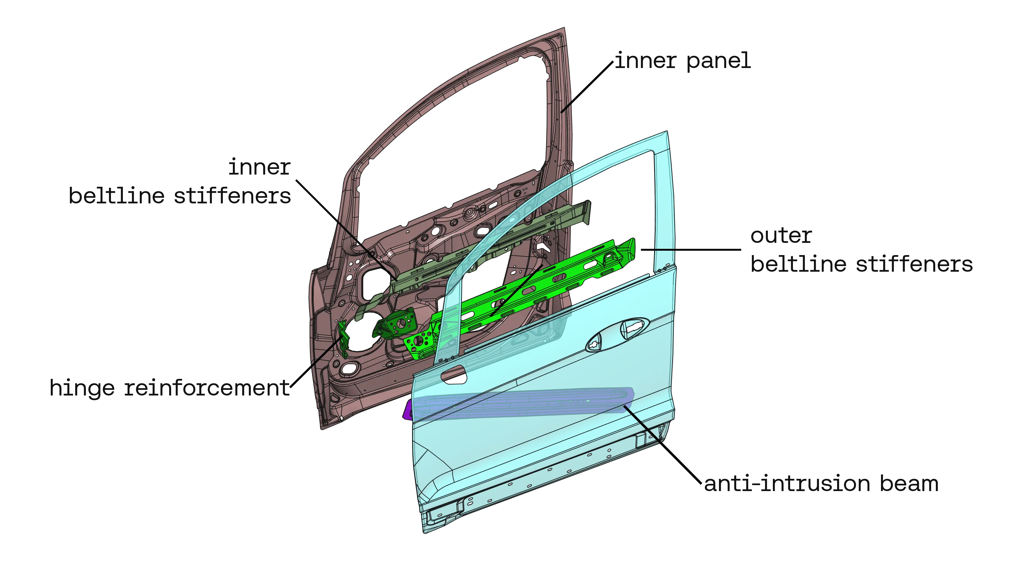
The position of the anti-intrusion beam is fundamentally bounded by the draw depth of the inner panel, while its terminations rely on specific geometry derived from the latch and hinge reinforcements. Concurrently, the upper geometry of the inner panel is both a constraint on and constrained by the beltline stiffeners.
Consequently, design decisions for any single component inevitably restrict the available design space for adjacent components across every shared interface. It is precisely this tight structural interdependence that necessitates continuous iteration in car door design.
To break this cycle, we must move away from the traditional, sequential approach where integration is treated as an afterthought. Solving the car door problem effectively requires a system that stops treating components as independent variables. This is the fundamental premise of the AURA reasoning engine.
How AURA composes the subassembly
Rather than evaluating couplings after component creation, AURA incorporates them directly into the initial problem specification. By treating inter-component couplings — load paths, geometric interfaces, and manufacturing sequences — as primary design variables, AURA acts as a powerful design assistant that automates the tedious, manual trial-and-error phases of early-stage engineering.
The result is a 90% complete, physically and geometrically sound baseline, allowing engineers to skip the frustrating cycles of basic spatial reconciliation and jump straight into high-value design refinement.
From an architectural standpoint, this capability is grounded in two core principles:
- Relational symbolic representation: the system captures relations between components, not just isolated attributes.
- Interface adherence: the geometry generation engine strictly adheres to external interfaces that it did not independently establish.
To establish these architectural concepts, this study focuses on the core structural elements of the passenger car door: the anti-intrusion beam and the inner panel. Operating as a coupled unit, the maximum section depth available for the beam is bounded by the panel's draw depth, whereas the panel's interfaces provide the necessary structural support for the beam's load paths.
Concurrently, the AURA engine faithfully observes the rigid constraints set by the surrounding vehicle frame. This defines a two-level coupling architecture: mutual two-way interaction within the panel and the beam(s), and one-way dependencies leading out to the fixed assembly. By integrating both structural layers, AURA creates manufacturing-ready parts that resolve the complete set of engineering constraints.
The value of AURA's automation
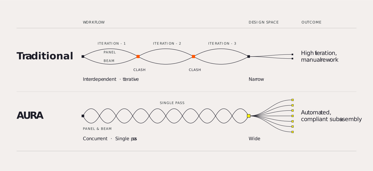
Before diving into the specifics of the car door problem, it is useful to contrast the traditional engineering process with the AURA approach:
- Traditional process: the inner panel engineer and the anti-intrusion beam engineer develop the designs interdependently assuming the interaction surface. Packaging throws a clearance error, CAE fails a side-impact load, and they spend three weeks passing CAD files back and forth to fix it.
- AURA process: a single, centralized, autonomous agent that takes the boundary constraints and load cases, and returns a geometrically valid, physics-compliant subassembly that is generated concurrently without the manual back-and-forth.
We can summarize this comparison in a simple table:
| Process | Workflow | Outcome |
|---|---|---|
| Traditional | Interdependent, iterative process, narrow exploration | High iteration, manual rework |
| AURA | Concurrent, single-pass approach, wide exploration | Automated, compliant subassembly |
Note: everything in this study is scoped to a single manufacturing process. All five components are steel stampings. Composing across heterogeneous processes is a different, more complex problem and is not addressed here.
The design
The problem setup
The broader objective is to design the major steel-stamped components of the door's structural subassembly together, against the fixed spatial boundary of the surrounding body-in-white. To keep the scope practical, we narrowed this study to its structural core: two components were designed simultaneously, the inner panel and the anti-intrusion beam(s), while the beltline stiffeners and the hinge and latch reinforcements were held at their original geometry. The design space was inherited from the BIW perimeter: the A- and B-pillar geometry, the rocker height, the hinge axis, the latch location and internal components to be avoided (e.g. speaker, cable routing). Every component is standard automotive stamped sheet steel.
The design had to meet the constraints imposed by two load cases on the whole assembly, while minimising mass:
| Parameter | Specification |
|---|---|
| Material | Stamped sheet steel: E = 210 GPa, ν = 0.3, ρ = 7850 kg/m³ |
| Thickness | Panel 1.0 mm, beam 1.5 mm |
| Target | Reduce overall mass |
| Constraints | Sag load case max displacement in z ≤ 1.5 mm; over-open load case max displacement in y ≤ 1.5 mm |
| Load cases | Applied at the latch | Measured |
|---|---|---|
| Sag | Downward (−Z), 1 MPa over the contact patch | Maximum vertical displacement |
| Over-open | Outward (−Y), 0.05 MPa over the contact patch | Maximum outward displacement |
For this study the engineer provides one CAD input. It fixes the contact geometries and the areas to be kept invariant in the generation of the panel geometry, and the areas to avoid while generating the new geometries.
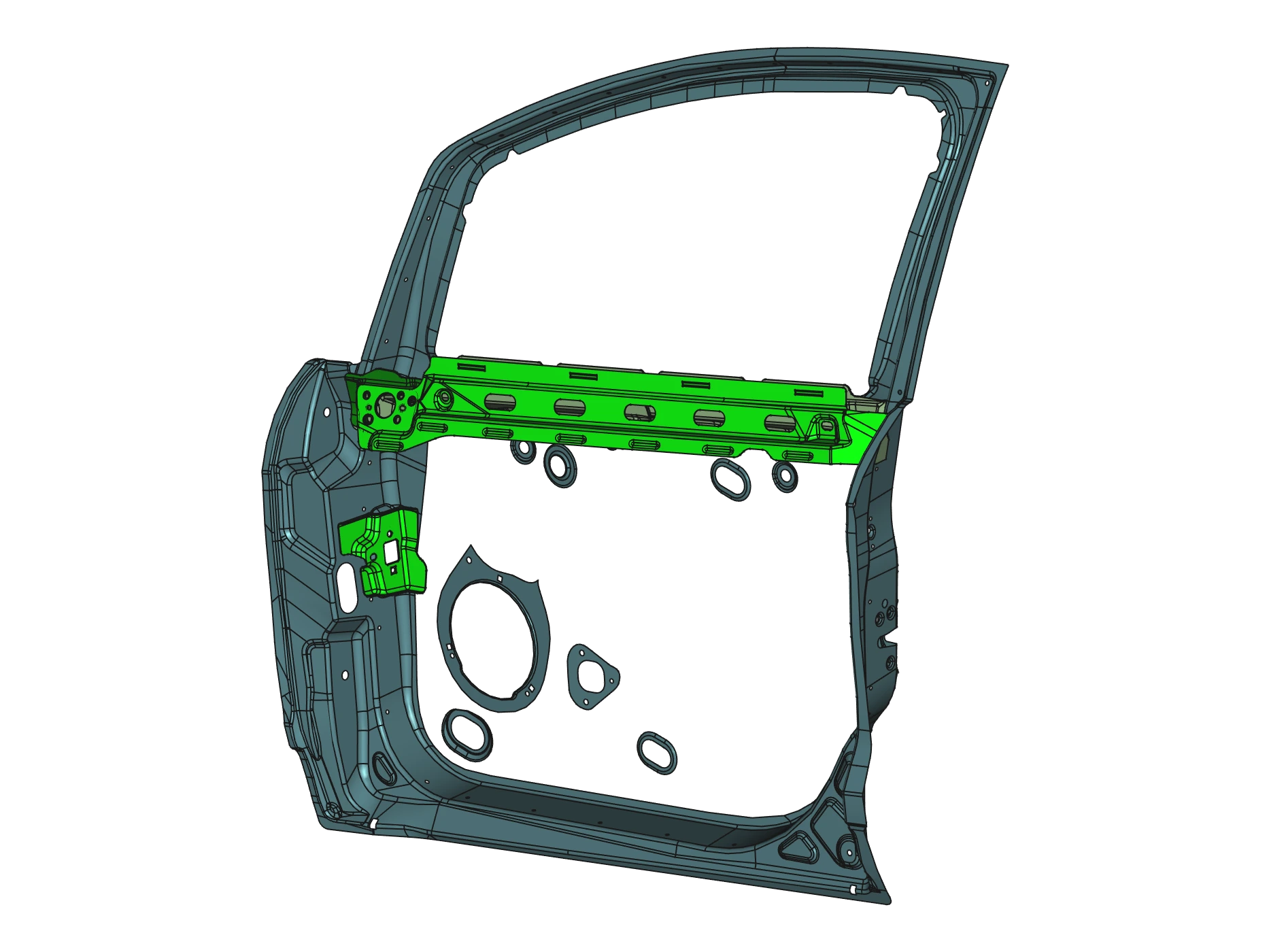
From that input, every subsequent decision is automatic. AURA determines how the parts relate, discovers where they make contact, generates the panel and beam geometry, and resolves it against the physics of the full assembly. The engineer does not place the contacts, choose the number of beams, or specify how the components divide the load.
To show the automation mechanism working it is worth dwelling on the beam-beam case. The beams are generated with spatial awareness of every part already placed, each new beam treating the existing geometry as a region to avoid. In the undeformed assembly the beams do not touch, and clearance is created so that contact under load is also avoided.
Generation runs and graph sequencing
Generation runs were then executed using topological orderings derived directly from a liaison graph:
[Non-Design Anchors] --> [Component 1] --> [Component 2] --> [Component N (most constrained)]
         |                     |                 |                          |
         +---------------------+-----------------+--------------------------+
envelope / avoid- Topological sequencing: non-design structural anchors serve as initial boundary constraints. Each design part is generated sequentially using the finalized geometry of its already-generated neighbors as rigid envelope and avoidance spaces. Downstream components become progressively more constrained, ensuring tight spatial fit.
- Heuristic selection and loops: automated sequencing heuristics determine the optimal generation order, for example, sorting design parts by increasing contact degree or sweeping along a global augmentation direction. Where tightly coupled interdependencies exist (such as balancing inner panel draw depth against anti-intrusion beam spine clearance), iterative generation loops allow earlier components to be re-generated against newly established interface constraints.
The result
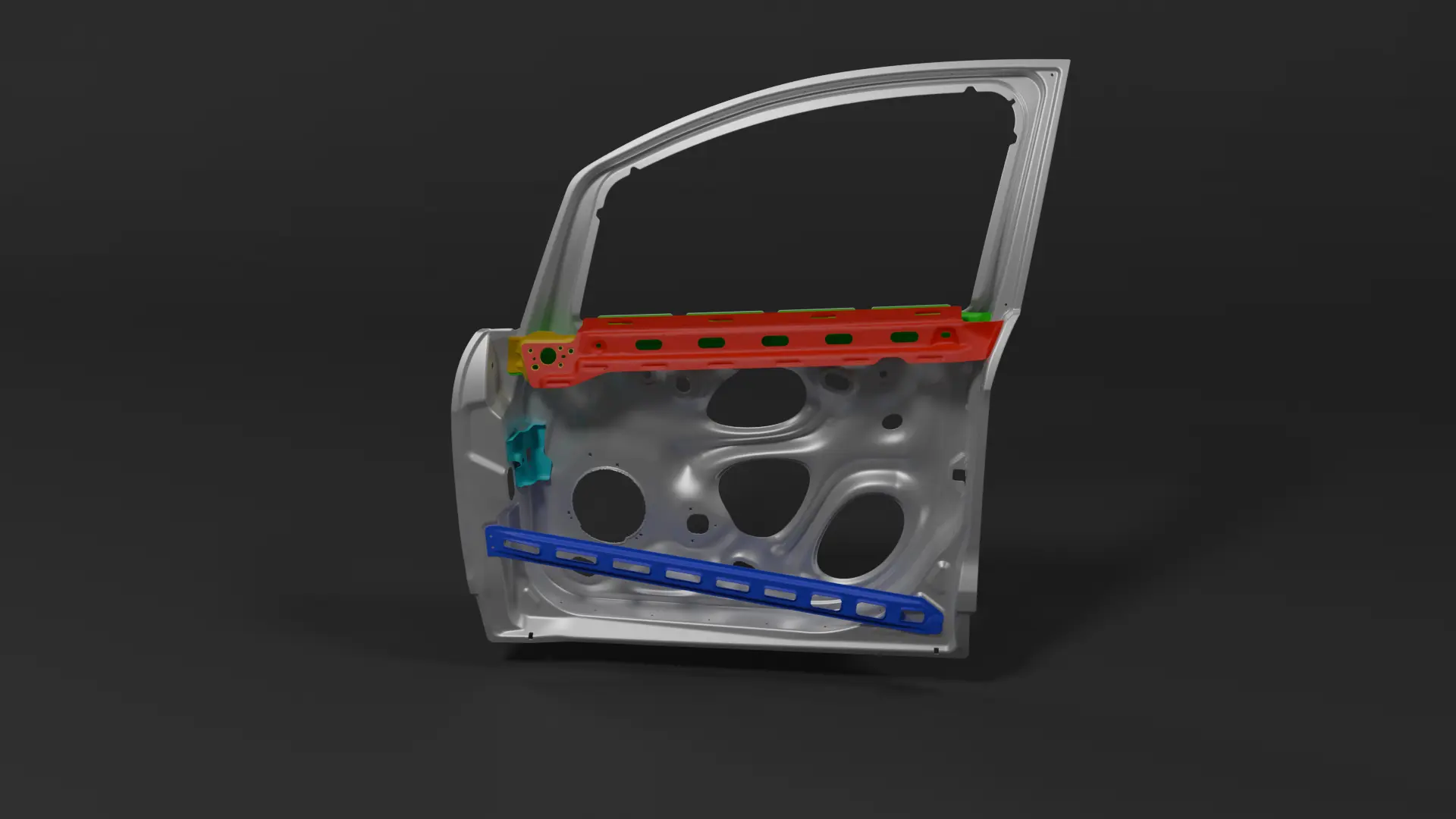
The generative process yields an assembly structure that successfully meets the requirements of both load cases while minimizing mass within the designated fixed envelope. Rather than fixing the number of anti-intrusion beams beforehand, the core architecture dynamically adapts based on structural necessity. If a single beam can successfully manage both the sag and over-open load cases within established limits, the system converges on a single-beam layout. However, if the competing physical demands require separate load paths, the core resolves into a dual-beam configuration to isolate and handle the forces independently.
Crucially, the entire generated geometry remains fully manufacturable and strictly adheres to the boundaries imposed by the surrounding fixed subassemblies. The outer section of the beam is directly constrained by the inner panel's allowable draw depth, and the load paths terminate precisely on the existing fixed reinforcements. The resulting output is a stampable structural geometry optimized specifically to fit the exact vehicle door framework under development.
Beyond the door
The passenger-car door serves as just one representative instance within a broader, extensive category of structural components. In these complex subassemblies, engineering cannot be done in isolation because the greatest challenge lies in managing the hidden web of inter-component constraints that bind individual pieces together.
A passenger-car hood represents another clear instance of this setting, featuring its own distinct geometry and load cases, such as an outer panel, an inner reinforcement structure, hinge and latch mountings, and a head-impact demand distributed across the reinforcement setup. Despite these specific differences, they share the exact same foundational architecture: a coupled set of components whose design spaces mutually bound one another. Because these interactions are primary design variables, the components cannot be designed independently and combined afterwards; instead, they must be generated simultaneously against a comprehensive collective framework.
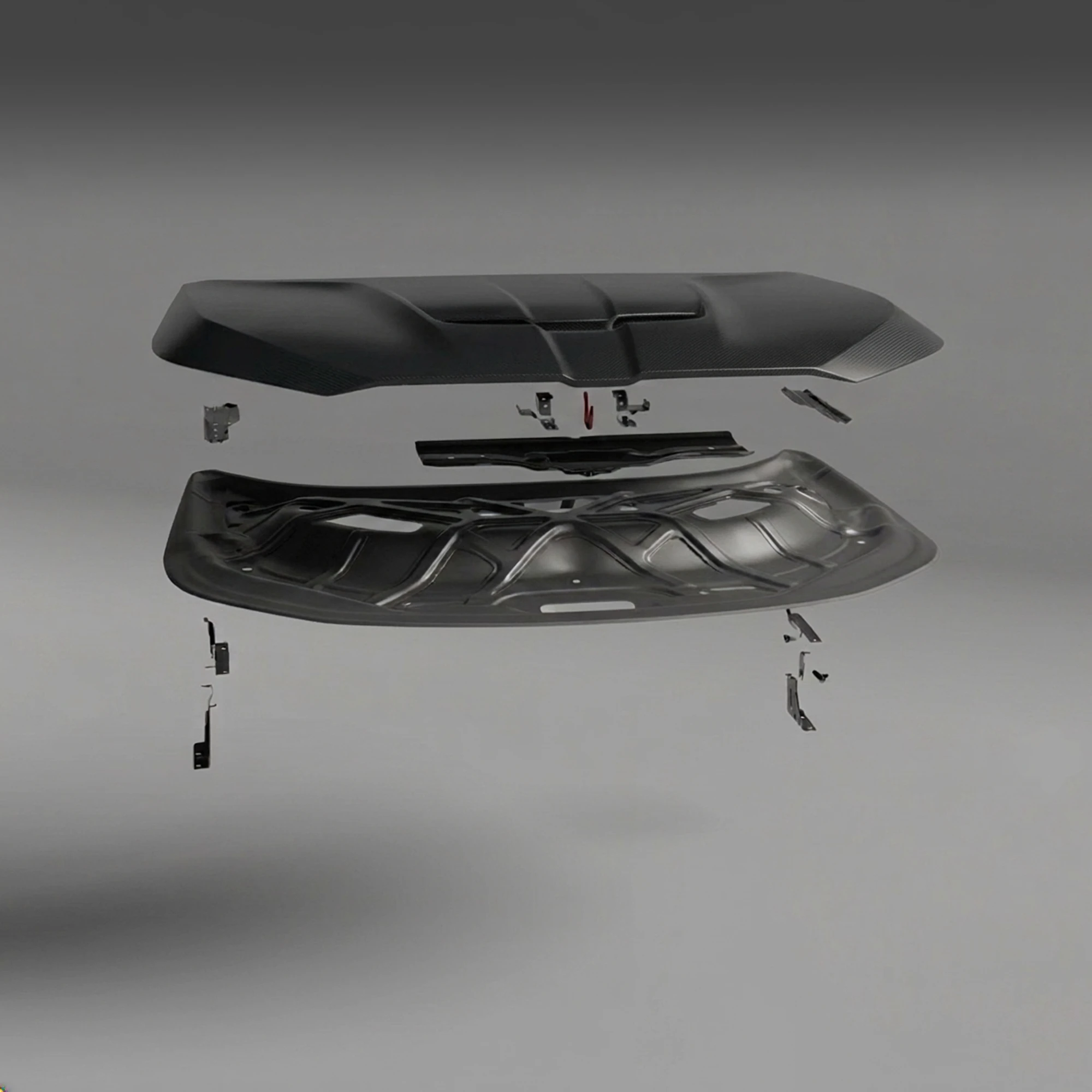
This category of coupled systems extends widely to include other automotive subassemblies such as floor pans, tailgates, and body-in-white (BIW) side panels. Beyond the automotive sector entirely, aerospace skin-and-stringer panels exhibit a similar character where the geometry of one component bounds the design space of the next, loads cross interfaces, and the manufacturing sequence imposes a strict order.
Ultimately, the core unit of work in this class of problems is subassembly composition, rather than traditional component-level generation. Within this framework, the car door serves as the primary representative example, demonstrating how the AURA reasoning engine can distribute constraint information throughout a network to ensure all components are compatible by design.
Talk to us about a deployment →
Scope and method
As an exploratory study rather than a customer deployment, this project treats the car door as a representative problem with simplified assumptions.
The study designs two components, the inner panel and the anti-intrusion beam, against each other and against the beltline stiffeners and the hinge and latch reinforcements, which are held fixed. It is a co-design of the structural core within a fixed assembly frame, not a generation of the whole door. Both designed components are steel stampings; the study does not address design across different manufacturing processes. Part relations and contact interfaces are determined automatically rather than specified by hand. Candidate geometries are generated from scratch and then optimized against two load cases, sag and over-open, that must be satisfied simultaneously, together with the fixed interface constraints, under full-assembly physics.
Contributors
Thomas Ghorbanian set up the problem definition in AURA and collected the data. Guido Cossu and Thomas Ghorbanian wrote the article. Eugene Antone, Alvaro Del Pozo and Antonio Bolea Albero reviewed it.